How to Read an Optical Drawing
An optical drawing serves as a comprehensive blueprint for the production of optical components and systems, based on specific design and performance requirements. It is condensed by optical designers and engineers and can be easily comprehended by manufacturers globally. ISO 10110 is widely recognized as the standard for optical drawing, as it outlines the geometric dimensions and tolerance specifications for all optical parts and systems. The below image illustrates the standard format of an optical drawing:
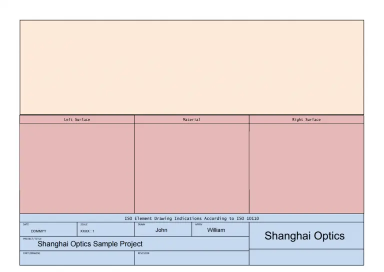
It is composed of 3 fields:
- Drawing Field (orange area)
- Table Field (pink area)
- Title Field / Title Block (blue area)
Here’s an example of an optical drawing
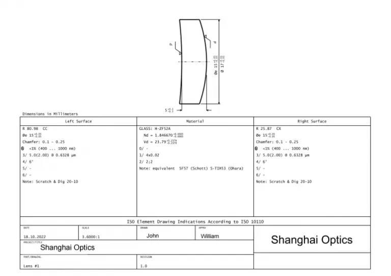
Let’s break down the 3 fields as mentioned above.
Field I — Drawing Field
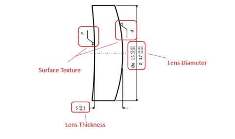
Shown on this drawing, we could find the detailed information of:
Surface Texture:
Describes the small, local deviations of a surface from the perfectly flat ideal plane.
P – means polished
Lens Diameter:
Physical measurement of the diameter of the front-most part of the lens.
Lens Thickness:
Distance along the optical axis between the two surfaces of the lens.
Now, we know this is a polished meniscus lens, how large and how thick it is.
Let’s move to the table field.
As in our example, this optical component has two optical surfaces, so the table field is broken into three subfields. The left subfield refers to the specifications of the left surface, and the right subfield refers to the specifications of the right surface. The middle field refers to the specifications of the material.
Surface Specifications:
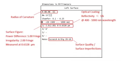
When describing the radius of curvature, we usually use CC as concave, CX as convex for the shape
Material Specifications:
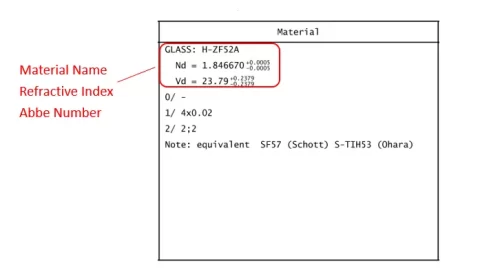
1/ : Bubbles and Inclusions
Usually written as 1/AxB where
A is the number of allowed bubbles or inclusions in lens
B is the length of side of a square in units of mm
2/ : Homogeneity and Striae
Usually written as 2/A;B where
A is the class number for homogeneity
B is the class for striae
Here we come to the final field: Title Field
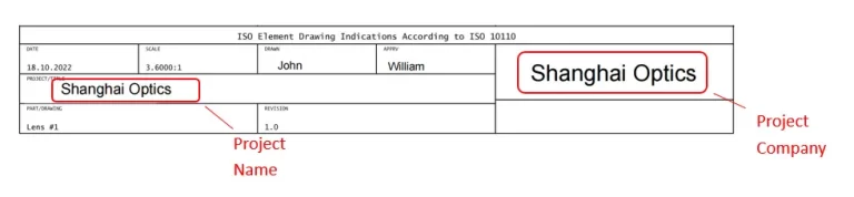
The “Title field” tells us the name of the designer/engineer, date, project name, and what the scale is. Sometimes we might see drawings with different expressions in specifications and in different units.